Line
Create line
The line can only be added to workspace from toolbar.
 from
from Note
If the toolbar is not displayed, it can be displayed from Settings > Display > Parts.
Line properties
Element part proterties can be displayed from information panel when the part is selected.
Note
If the information panel is not displayed, it can be displayed from Settings > Display > Information.
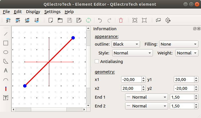
Figure: QElectroTech line from element
QElectroTech allows customizing different line properties:
- Appearence
- Color
The outline and filling color of the part can be defined from a list of pre-defined colors. At the case of the line part the filling color is None.
- Style
The outline representation type can be chosen between: Normal (Continuous), Dashed, Dotted or, Dots and dashes.
- Thickness
The outline thickness (Weight) can be chosen between: None, Thin, Normal, Strong or High.
- Geometry
- Coordenates
The start and end point coordinates (x, y) can be defined.
- End point
The extrem point from the line can be represented individually as:
- Normal
The extrem point is represented as the rest of the line, there is no different representation for the end point.
- Simple arrow
The extrem point is represented as a filled arrow.
- Triangle arrow
The extrem point is represented as an empty triangle arrow.
- Circle
The extrem point is represented as an empty circle.
- Diamond
The extrem point is represented as an empty diamond.